
Project Development
- isabelleadora
- Feb 19, 2023
- 8 min read

Throughout the module, we were supposed to create a prototype of our chemical product. In this blog, I will showcase my journey in building this prototype. It will consist of what my team's chemical device is, the design & build process, and the problems we faced and encountered.
Our team's chemical device
Our team chemical device is a breathalyzer that is called 'Save a breath, save a life'. The purpose of our team's chemical device is to prevent drunk driving. Drunk driving is more common than we think it is and can lead to many fatalities and injuries. Based on a Forbes article, 28 people die from drunk driving according to the National Highway Traffic Safety Administration (NHTSA). In Singapore, one of the main causes of car accidents is due to people driving drunk. Hence, we want to eliminate car accidents that are caused from drunk driving. The team's chemical device is a breathalyzer and it works in such a way that when it detects an alcohol level that is considered as drunk, it will alert the driver he is not supposed to be driving through the usage of LED lights and a buzzer. The red LED will light up and the buzzer will produce an alarm to shock or annoy him so he will not continue driving. To actually prevent him from driving, we have a mechanism that will block the keyhole so that he cannot start the car. When the driver is not drunk, the green LED will light up and the mechanism will unblock the keyhole.
The hand sketch of our chemical device is shown below.

Team Planning, Allocation & Execution
My team members and their allocated roles
Lee Yeung Juen - CEO
Mavic Chin - CFO
Alvin Chuah - CSO
Isabelle (me) - COO
Finalized BOM

Finalized Gantt Chart

Design & Build Process
Part 1: Design and Building of Cardboard Prototype (Done by everyone) We had a general idea of how we wanted our device to look like but to actually design it on computer, we needed to know the correct dimensions to do so. Hence, we decided to do cardboard prototyping first.
While Alvin and I worked a bit on how the parts will look on the arduino, Yeung Jeun and Mavis drew out how all the parts will look on the cardboard.
We then realised we need a hole for the arm of the servo to move and cut it to size.

This is how it looked like after and we took the measurements to aid in our compurter aided design.

From this though, we realised the LED will not be seen as it does not reach the casing and we amended it by connecting it to a female jumper wire.

Part 2 & 3 : Making the CADD design and Designing the mechanism (Done by Yeung Juen: https://cp5070-2022-2b04-group4-leeyeungjuen.blogspot.com/p/project-development.html)
The CAD Design of Device

The CAD Design of Mechanism

Visit his blog for more details on the designing process.
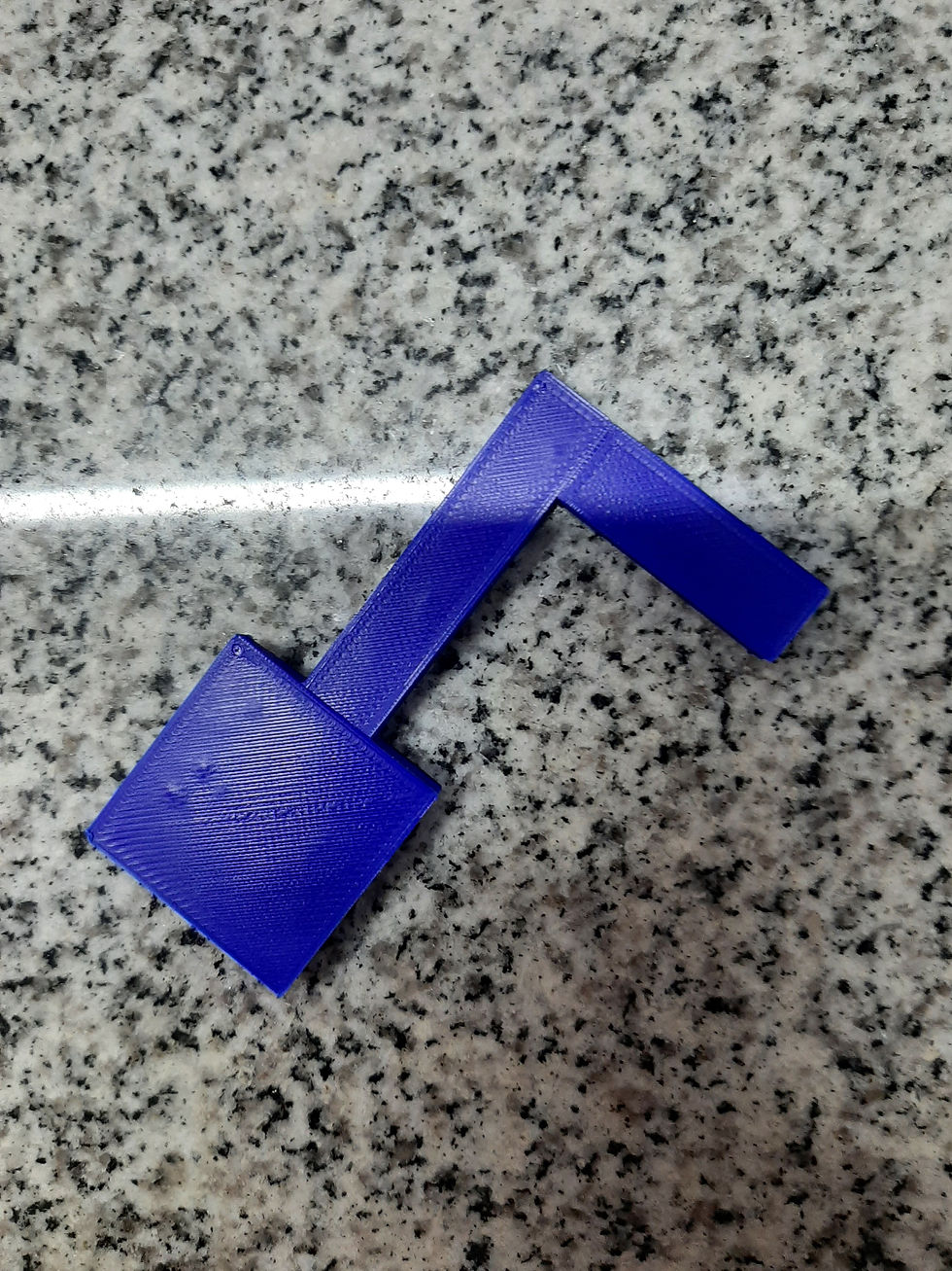
Part 4: 3D printing of mechanism (Done by Mavis: https://cp5070-2022-2b04-group4-mavis-chin.blogspot.com/p/project-development.html & Yeung Juen: https://cp5070-2022-2b04-group4-leeyeungjuen.blogspot.com/p/project-development.html) Initial 3D Printed mechanism

Finalized 3D printed mechanism
Visit their blogs for more details on the 3D printing process
Part 5: Designing box faces of casing for laser cutting (Done by Mavis: https://cp5070-2022-2b04-group4-mavis-chin.blogspot.com/p/project-development.html)
Box Design For bottom:

For top:

Visit her blog for more details on the designing process.
Part 6: Laser cutting (Done by Alvin: https://cp5070-2022-2b04-group4-alvin-chuah.blogspot.com/p/project-development.html)
Laser cutted parts

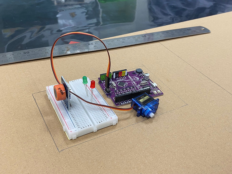
Visit his blog for more details on the laser cutting process. Part 7: Programming of electronics (Done by me) Process I was in charge of programming the electronics and that were 4 main things that I had to code; the LED, Servo, Buzzer and Alcohol Sensor. From part 1, when trying to design and build our cardboard prototype, we had already started with trying to get a reading from an alcohol sensor and getting the LED to turn green when alcohol readings are low and turning red when alcohol readings are high. As shown below, it was a success.
The youtube tutorial that I referenced the code for the MQ3 Alcohol sensor was https://youtu.be/f6uldsZ7SAI
However, after dismantling and trying it out the next week, we wanted our code to be simpler as it got quite complicated when trying to add on the codes for the buzzer and servo. So, we used a different video for reference for the MQ3 alcohol sensor code. The video is https://youtu.be/EIzXsAIJrO4 , but we still had to add on our own code for the buzzer and servo, which we referenced from previous lessons. We also managed to get everything to work but we realised that originally the keyhole will be unblocked and the servo will only turn to block it when alcohol is detected. We thought this was dangerous as a driver could still start the car without breathing through it and carry on driving whilst not caring about the blaring alarm or red light.
Through trial and error, we managed to get values for drunk and not drunk by breathing to the alcohol sensor. So, when they first start the car, the keyhole will be blocked and the servo will only turn after reaching a 'not drunk' value after a certain period of time. We were content and satisfied after running the code.

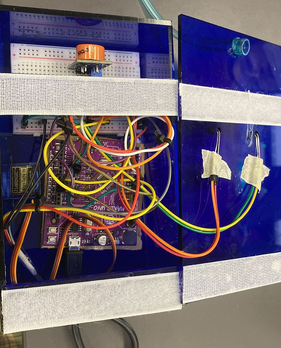
Also, alot of the times, the wire came out and we were confused on what detached. We solved this through compartmentalizing our wires.

Above is our wiring and we used zip ties to split up our wiring to their own respective parts. For example, the wires (green & yellow and orange & red) going to the cover of our box are to the red and green lights respectively. The red, yellow and grey wires are to the servo on the top box. The orange, yellow and white wires are to our alcohol sensor. This made it easier to know the wires for which electronics were out of place and quickly amend it, instead of redoing the wiring again.
Final Code
const int AOUTpin = A0;
int sensor_value = 0;
int LED_green = 10;
int LED_red = 11;
int Buzzer = 8;
#define NOTE_DS8 4978
// notes in the melody:
int melody[] = {
NOTE_DS8, NOTE_DS8, NOTE_DS8, NOTE_DS8, NOTE_DS8, NOTE_DS8, NOTE_DS8, NOTE_DS8, NOTE_DS8, NOTE_DS8
};
// note durations: 4 = quarter note, 8 = eighth note, etc.:
int noteDurations[] = {
4, 4, 4, 4, 4, 4, 4, 4, 4, 4
};
#include <Servo.h>
Servo myservo; // create servo object to control a servo
int pos = 90; // variable to store the servo position void setup (){
Serial.begin(9600);
pinMode(LED_green, OUTPUT);
pinMode(LED_red, OUTPUT);
myservo.attach(9);
myservo.write(0);
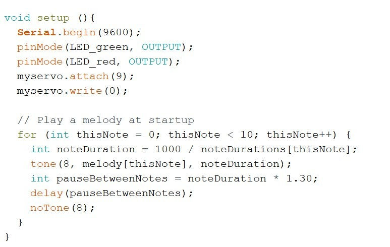
// Play a melody at startup
for (int thisNote = 0; thisNote < 10; thisNote++) {
int noteDuration = 1000 / noteDurations[thisNote];
tone(8, melody[thisNote], noteDuration);
int pauseBetweenNotes = noteDuration * 1.30;
delay(pauseBetweenNotes);
noTone(8);
}
}
void loop (){
// Read the analog input from the sensor
sensor_value = analogRead(AOUTpin);
Serial.print("Recorded value:");
Serial.println(sensor_value);
if(sensor_value < 700){
// If the sensor value is less than 700, turn on the green LED and move the servo to 180 degrees
delay(200);
digitalWrite(LED_green, HIGH);
digitalWrite(LED_red, LOW);
digitalWrite(Buzzer, LOW);
myservo.write(180);
delay(15);
}
else if(sensor_value > 800){
// If the sensor value is greater than 800, turn on the red LED, sound the buzzer, and play a melody
digitalWrite(LED_green, LOW);
digitalWrite(LED_red, HIGH);
digitalWrite(Buzzer, HIGH);
int melody[] = {NOTE_DS8, NOTE_DS8, NOTE_DS8, NOTE_DS8, NOTE_DS8, NOTE_DS8, NOTE_DS8, NOTE_DS8, NOTE_DS8, NOTE_DS8};
int noteDurations[] = {4, 4, 4, 4, 4, 4, 4, 4, 4, 4};
for (int thisNote = 0; thisNote < 10; thisNote++) {
int noteDuration = 1000 / noteDurations[thisNote];
tone(8, melody[thisNote], noteDuration);
int pauseBetweenNotes = noteDuration * 1.30;
delay(pauseBetweenNotes);
noTone(8);
myservo.write(90);
delay(0);
}
}
}
Explanation of code

First, we define and declare the constants and variables that we will use. A0 is defined as ‘AOUTPin’, and we initialise the green, red and buzzer to a pin number. The sensor value is also initialised to read 0 as an integer number. We also defined ‘NOTE_DS8’ as the frequency 4978 hz to play in the melody.
We then establish the outputs, which are green LED, red LED and servo.
At startup, we play the melody and set the servo position to 0. When we first power on the Arduino, we set the amount of notes to 0 and if it is less than 10, we play a note.The duration of each note is 1000ms and we also add in a pause between each note.

After the set up is done, the loop function will run repeatedly until off. In this function, it reads the analog input from our alcohol sensor and is stored as ‘sensor_value’, whereby the value is printed on the serial monitor.
If the sensor value is below 700, the green LED is turned on, the red LED is off and the servo position will be set to 180 degrees (unblocks the keyhole).

If the sensor value exceeds 800, red LED will be turned on, green LED will be turned off, buzzer will start playing the melody, and servo position will be set to 90 (blocks the keyhole).
Part 8: Integration of parts and electronics (Done by everyone)
We first tested out whether all our printed and laser cut parts managed to fit our electronics. The laser cut holes to fit the servo and our USB cable did not fit so we had to file it down until it managed to fit.

Then we had to glue all our acrylic pieces together to encase our arduino, breadboard and the electronic parts inside.

After which, we placed the breadboard and the arduino inside the box using doubke sided tape. The servo, LED lights, USB port and tubing was placed in the corresponding holes that we cut out on the box. We also used velcro as way to close the box.

This is how our final product looks like and the team with it!


This is a short demo on how our product works with an alcohol wipe that represents someone drinking.
Problems & Solutions
Problems we faced and how we handled it
It took a long time for the alcohol sensor to register when alcohol was being blown as the tube was too long. Originally, it was 1m long and there was supposed to be a face mask but we decided to do without it and make the tube shorter.
We originally wanted to glue hinges and locks on the box but it could not stick onto the acrylic box. We also could laser cut holes to screw on the hinges and locks as the screw was longer than the thickness of the box and it would not fit right. What we did was using leftover pieces from our cut acrylic, gluing it on top of the open box and placing velcro, which is what our TE suggested we do.

Project Design Files as downloadable files
You can download our files at this link: https://drive.google.com/drive/folders/1n0YuJPGEfWOcfRCZGTegWV-Y-H6t1ZvF?ths=true
Learning Reflection
From this project, I learnt more on what it means to actually create a product. In ICPD, I thought it would be just designing and then making it. But in CPDD, it made me realise there are alot of considerations that we have to take note of like the BOM as realistically, our budget is not unlimited and using a Gantt chart so that we are actually on task. I also managed to learn more in terms of programming and the skills I learnt for that will definitely be useful for my FYP and also in the future as tech is an up and coming industry. Though I learnt a lot for programming, the same could not be said for CAD, 3D printing and laser cutting. For CAD, I find that it is quite incredible to see my groupmates designing something on the computer look quite similar to the one in real life. Hence, I would want to learn from them before our FYP. I think one thing that we have definitely gathered as a group is that life is really unexpected and we can't expect things to always go our way. But we overcame this by being adaptable. On the last week whereby we were rushing and there was no more time for do-overs, the hinge problem really got us stuck as it was one of the final steps. We sat down as a group, discussed the possible solutions and with the help of our TE, we found the best solution that we could do - using velcro. I believe that our product does not look so bad considering we only had a few weeks to do so. If we were to redo everything again and had time to do so, we would learn from those mistakes and amend them.
All in all, this project not only taught me technical skills but also soft skills that will help in many more projects to come in intern and FYP. I would like to thank my groupmates for being a delight to work with. Although we have a few disagreements here and there, at the end of the day, we managed to work it out and successfully saw our product come to life.

Comments